Bicycle |


Abstract | |
| Welcome to the next technical project's documentation by ZWZ! You will be introduced to the process of the making of an electric drive for a bicycle. This is no new discovery, but off-the-shelf bicycles are either of poor parameters, or too costly. The method stated herein will indeed let you save some money and get yourself a unique piece of hardware, but if you do decide to make this real, you will have to put much time in this and stir the bottom of your handyman heart. |


Components | |
|
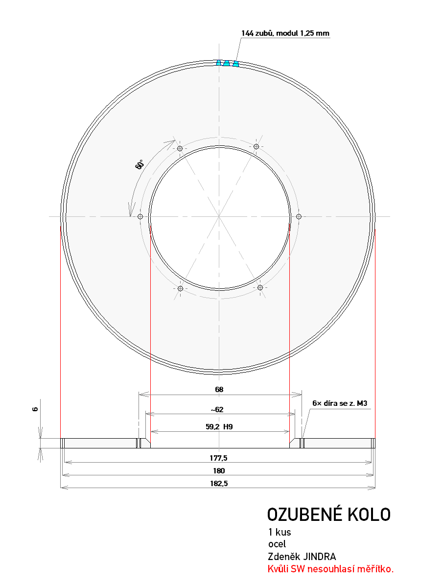
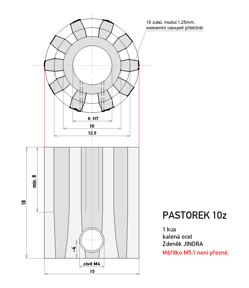
Please check this list of the required properties of your bike prior to any purchase so that it is compatible with the project. It is best to already buy a bike with these in mind. • Men's frame with triangular shape. This excludes most frames with rear wheel suspension. If you insist on a non-triangular frame, you will need a rear bracket with a carrying case. Otherwise get a regular triangular frame. • Rim brakes. The gear mounting method used here is incompatible with disc brakes. • Suspended front fork. These have a more regular and comprehensible cylindrical shape so that you can make the needed clamps easier. Furthermore it is simpler to evaluate the free space needed for the gears or pulleys since the buffers run parallel. In case of fixed iron fork, you may attempt to weld the motor mounting to it directly. (Not tested!) • Cutout on the insides of the buffer cylinders for the freewheel and gear wheel. I.e. Suntour NEX 4000. • The same count of wires for which a rear threaded hub can be purchased. You will need to weave a new rear hub into your front rim. Buy one with the same number of holes (mine had 36). It is needed to replace the axis of this hub first so that it fits in the front fork and hopefully has quick release too. The clear span is 100mm which may need to be tuned with a washer added to the right, geared side of the hub between the conical nut and the ribbed face nut during the assembly of the hub axis. • Equal size of wire attachment disc, otherwise you will need to purchase different length of wires too. Given that you already have a compatible bicycle, you can start ordering the drive components: • Motor. Do pay special attention to the choice of this component. Due to the out-of-ordinary nature of this project only the use of model outrunners will be described herein. No hub motors will be discussed as this competes with them both by price and by performance. I have found out that the smallest motor that suffices for a good ride is the AXI 4130/20 (a cheap replacement is a Turnigy TR 50-65-C, pay attention to the different shaft diameter), however, if you want a real joyride or if you plan to drive in the hills, you will prefer the Turnigy TR 63-54-A, or the extreme Turnigy C63-74. Unfortunately, one cannot rely on Turnigy's statements about permissible loads, so consider the maximum current being 1A per each 10g of motor mass. Supply the AXI with up to 76% of the maximum current stated as a burst 60s current. • Rear threaded hub or planetary hub gearbox (this does not require the freewheel). • Freewheel 18T meant for obsolete bikes with single gear ratio. Its inner threading fits the hub and the outer cylindrical part's diameter of 59.3mm fits the large gear wheel as described in the drawing below. • Bespoke gears or pulleys. My drawings are for a version without the gearbox nor the belt so that you may need to design your own. The pinion has a 6mm, H7 hole fit stated on the drawing, but you may change that to 8H7 or 10H7 for the Turnigy. Furthermore it is needed to adjust the number of teeth for these motors as described further below. • Battery. Find a cheap dealer of Lithium-polymer batteries. I bought these, but should you need a different number of cells than 3 or 6, try to buy the cells of type CSL6844127D or similar directly from a Chinese manufacturer BYD. Fill the designated space in the frame or the back carrying case with as many cells as possible. I ended up with 4S10P, 16V, 32Ah. • Brushless model speed controller (ESC). I have used a 85A version of the Mystery Blue line, but it seems that these have problems starting with batteries having more than 3 or 4 cells. • Plugs and cables. Take care about sufficient crosssection. I used 4×1,5mm2 of copper (that's 4×16AWG or 2×12AWG or even not recommended 1×10AWG) and 2 fastons for each pole. (You need another set of heavy wires for the other pole, I recommend buying a red and a black group.) Conductive loss is around 3%. • Charger. I am using the Xtrema product, but its firmware is not perfect and it's rather expensive for what it does. It however still supplies the highest current on the market: 8A. Never attempt to charge lithium batteries with car battery chargers! • Servotester. Choose the cheapest model controlled by a potentiometer only. This circuit accepts the voltage from the potentiometer in the range between 0 and 5V and produces a pulse-width modulated signal that controls the controller's throttle. It is needed to modify this circuit - solder away the pot, connect your own and, most importantly, connect the current limiter. This one has proven to be necessary after numerous tests. |
Installation | ||
|
The gears being the hardest to get, you should obtain them soon. Their dimensions, however, depend on the means of the hub drive and on the motor's axis. Because of that, you need to get the hub with or without the planetary gearbox (requires changes in the drawing). Decide which motor to get (AXI 4130 - 6mm hole, other motors - 8 or 10mm). Adapt the hub or gearbox axis so that it fits in the front fork. Make sure that the freewheel doesn't rub on the right inner side of the fork. Then get the gears according to these drawings:
An example of the pinion teeth recalculation: We start with 10 teeth, ×1,5 (inverted Kv), ×2/3 (inverted voltage), ×2 (double the current), ×0,75 (higher saturation - we may overload less). The result is 15 teeth for the Turnigy C63-74 motor. After getting the gears it is possible to test-mount the hub with the gear to the fork and to suggest the position to attach the motor in. I have used the lug originally intended for the mud-guard wire to attach the bottom end of the motor mounting (blue in the photos) and I fastened this to the suspension cylinders above with clamps (green). I made the mounting out of a 5×50mm steel belt, however, if you decide to use the larger motors, you will need a 60mm wide belt. The clamps are made of 10mm thick hard steel that was quite hard to work. At least it holds better in the end. I will leave the exact shape of the mounting on you because it depends on the fork, motor, gear ratio and belt used. Next, attach the ESC onto the fork near the motor. The phase wires should not be extended, so extend the battery wires and the thin 3-lead plug to the servotester. When fashioning the battery connector, tap the negative terminals with a thin wire. If you use more than one pin for a single pole as I do, connect a resistor of the same value (4R7) to each negative pin and later connect the free ends of these resistors together with the tap wire. It will be useful for the measurement of the flowing current and the power line between the battery plug and the ESC will serve as a shunt. I am adding a schematic diagram of the overcurrent protection below: 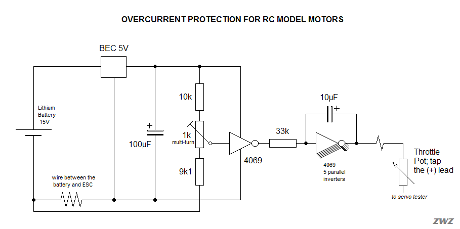 Diagram updated 5-10-2011. This protection solution is very simple, cheap and reliable. It may be used in other hobby applications; many people intend to install outrunners into various Dremel drills and many other machines. An overload protection is due. I have tweaked the circuit to the present revision, thoroughly tested it and it passed. The current did stay within ±2% of the desired value throughout the whole braking range. I managed to mitigate strong undesirable oscillations of the system by the introduction of a 10μF capacitor in the negative feedback of the final stage inverting amplifier. I tuned the circuit to the proper maximum current using an RC wattmeter. I held the wheel in the air, pulled the brake and read out the values. The protection circuit is constructed using a universal PCB and it is packaged together with the servotester. The plug pins and socket are gold-plated, the pot is multi-turn, the soldering side of the PCB is covered with hot glue. The box is connected via 3 wires to the ESC (power and output), one current-sensing wire to the battery plug and three wires to the throttle pot. The battery is the next taxing part. I didn't find a better shop than DX for this purpose, but I needed a 4-cell battery for this purpose, so I had to disassemble the batteries and connect them as 4-cell. I would recommend that you make use of the 6-cell system as described in the calculating example. If you want a less aggressive system, you can make a 3-cell battery and choose the AXI 4130/16 motor so that it's not too slow with voltage this low. Then I had to join the batteries into a single large one that would fit the frame. The battery obviously has all the appropriate balancing leads interconnected and output so that a balancer can be used properly. All is glued with hot glue gun and tape. The battery is equipped with straps and trident-style buckles to attach to the frame. Since my bike also had bowden cords on the underside of the top frame bar, I also had to make a metal shield over them so that the battery won't touch them. The battery output wires are terminated with automotive-style Faston block of pins. Each main pole is connected using two 12 AWG (3mm2) wires and the balancing leads are 0.75mm2 each. The last part not yet mentioned is the throttle pot. It may have any value between 1k and 10k. I was lucky enough to salvage a push-button STILL pot from the handle of a forklift. It is dustproof and the resistive layer is on quality ceramic substrate. A fix with conductive fluid was required, however, as these pots have fixed resistance of 500Ω on the stops which don't work well with the servotester. You won't probably find this particular pot, so use your imagination. |
Ride | ||||||||||||||||
The bike is fully equipped and you can take on the road. The weakest motor mentioned goes about 32km/h (20mph), the fastest one promises up to 45km/h (28mph)! The gears are designed for operation on table land. During the driveaway up to 15km/h or uphill the overcurrent protection will kick in and you must help by pedalling or pushing shift down. If you are about to ride this in a mountain area, you should decrease the pinion teeth count by one third, that is 10 teeth with the strongest motor. It is not possible to get a lower number due to bad geometry of teeth.
|
||||||||||||||||
Gallery | |
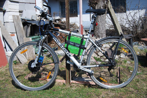 View at the bike 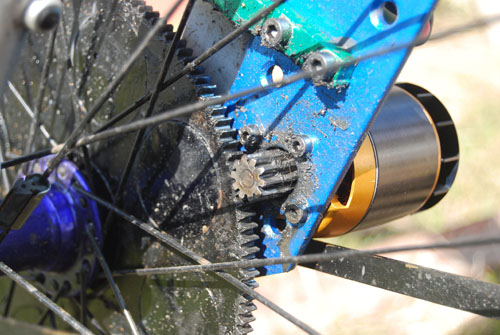 Gear detail 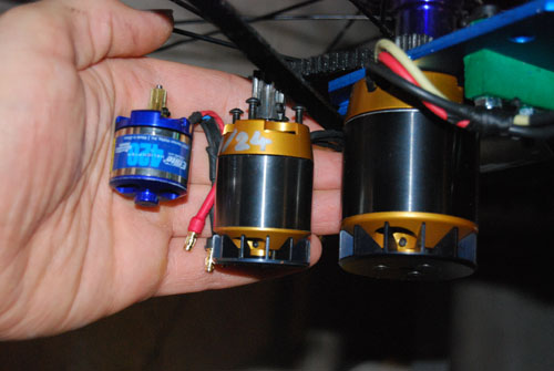 Outrunner comparison |

© ZWZ, 2011.  Some rights reserved.
Some rights reserved.